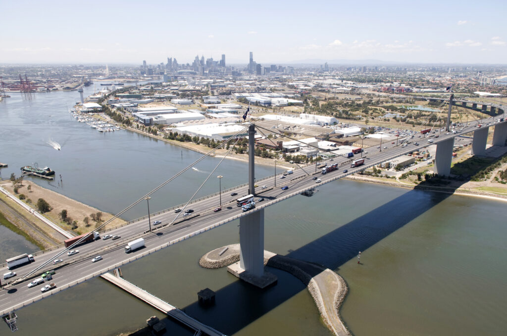
West Gate Bridge crosses the mouth of the Yarra River in Melbourne, Australia and forms a vital link in Melbourne’s main East – West transport corridor, the whole of which has undergone a substantial upgrade to provide increased capacity.
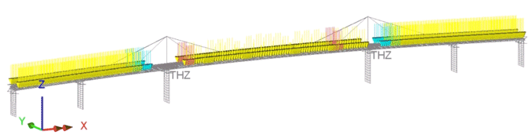
Using LUSAS bridge analysis software, COWI undertook global and local finite element modelling to analyse methods of strengthening the steel box girder for increased vehicle loading, by cantilever propping, internal stiffening, and post-tensioning; and for the management of construction loads.
Project info
Structural Engineer: COWI
5-span cable stayed steel box girder bridge
336m main span
4m deep continuous steel box girder
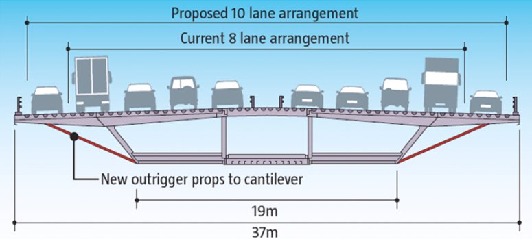
37m overall width including cantilevers
The strengthening solution adopted was to prop the existing cantilevers and turn the existing hard shoulder into a running lane. As well as propping of the cantilevers, a large amount of internal strengthening to the deck and towers was required to cope with the additional traffic loading.
For the permanent loadcase a survey carried out in 2007 showed that the central span of the bridge had deflected by around 330mm over the years due to the creep and sagging of the cables. Although the stretching of the cables didn’t change the tensions in them very much it did add considerably to the stresses in the deck when sagging at mid-span and when hogging at the towers. In the LUSAS assessment model the initial stress in the cable stays was adjusted to represent creep and the deck profile was matched to that of the 2007 survey. An as-built profile was also modelled to allow re-tensioning of the cables in the future.
For live loading, the traffic load definition was specific to West Gate Bridge and was derived from weigh-in-motion data where the weights of vehicles crossing the bridge were recorded and analysed to derive the extreme loading. Traffic loads were generated using traffic load optimisation software which required the creation of over 700 traffic loadcases to assess maximum stress along the box girder, and in the bearings and cables. For wind loading static loadcases were derived from the gust buffeting response of a spine model.
Because of the history of the bridge the handling of the construction loads was a particularly sensitive issue, made all the more difficult because the bridge was overstressed under the existing eight lane traffic loading. For reasons of safety, it was required to position concrete barriers along the bridge during the upgrade works which added considerable weight. It was decided to limit the loads during construction to the maximum theoretical 8 lane loading before the strengthening had started.
Modelling of construction loading
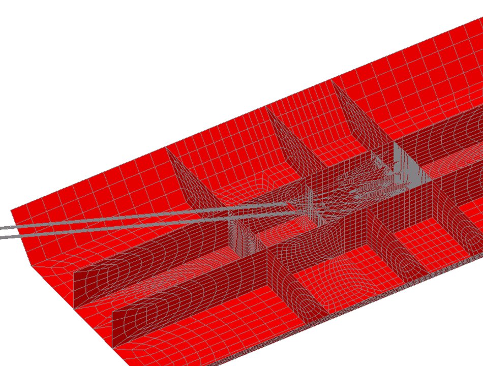
Detailed modelling around cable anchorage
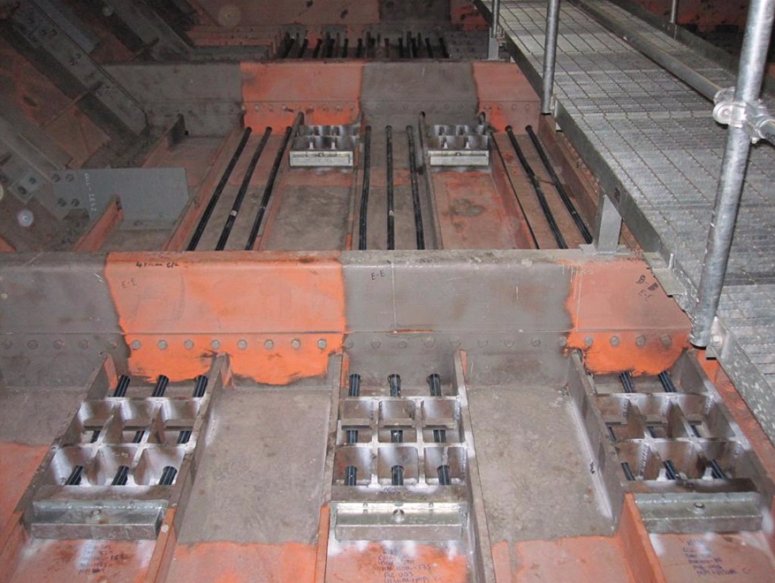
Stresses in anchorage plates
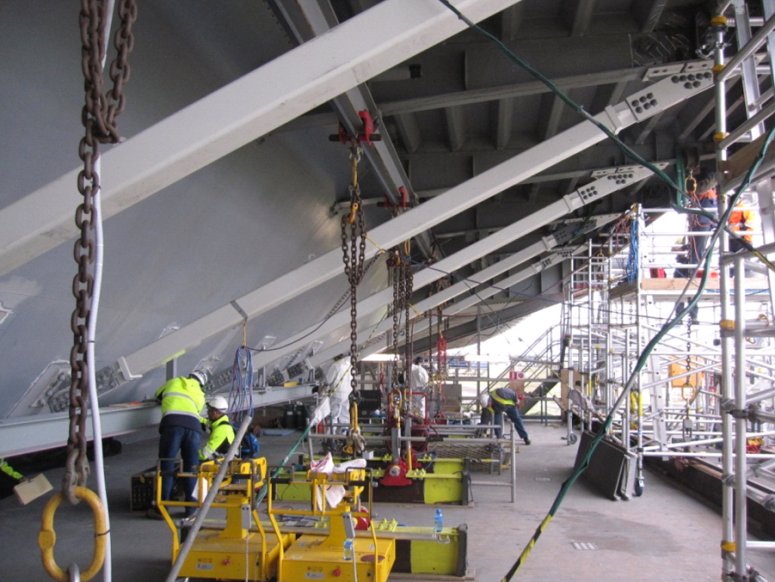
Installation of cantilever props
Prestressing of bottom flange
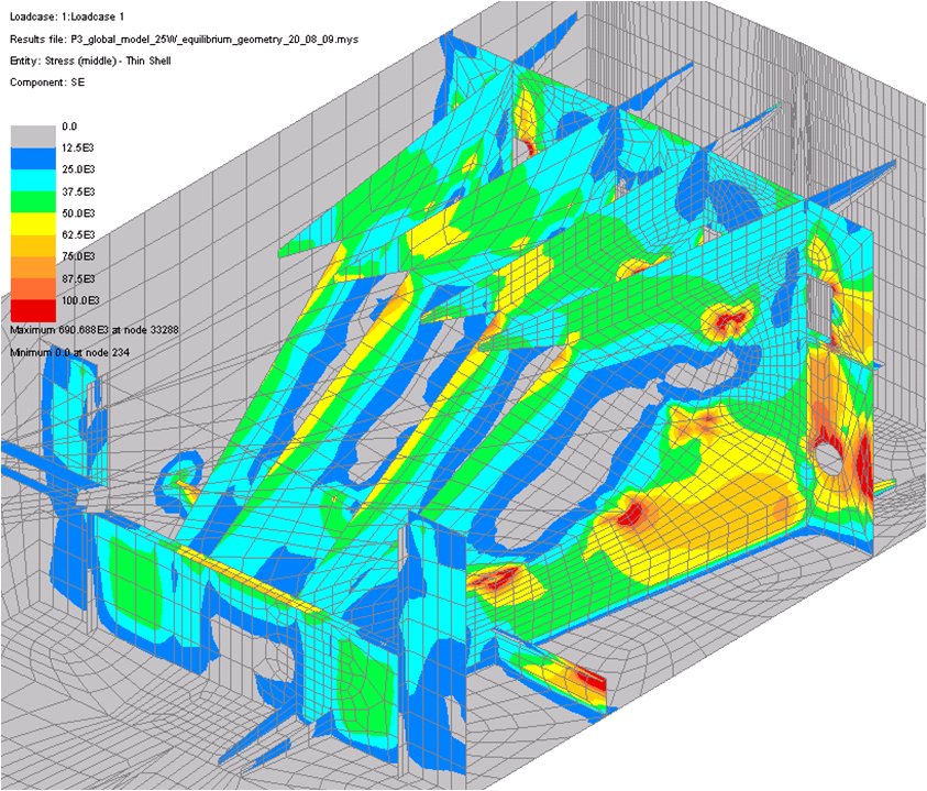
The use of a shell model of the whole bridge, allowed straightforward refinement of the mesh in certain areas of interest to investigate localised effects and also showed how the distribution of loads in the webs and diaphragms of the anchorages took place.
Localised modelling and nonlinear analysis with LUSAS improved the torsional buckling capacity of the bulb-flats beyond codified values resulting in a reduction of the strengthening required being obtained.
The outside of the bridge saw 528 cantilever props added, along with substantial strengthening carried out inside the box to the bottom flange and webs. This took the form of extra stiffening to the existing stiffeners and the addition of some new stiffeners. The box walls and diaphragm around the pier bearings required heavy strengthening in an already congested area. Prestressing strands were also used inside the box girder to overcome tension overstress in the bottom flange plate and overstress at the splice plates. The prestressing extends over a 60m length of flange, passing through holes drilled in the flange stiffeners, with plated anchorages at each end.
Additional stiffening of the towers was also required requiring the fitting of new plates in the region where the tower penetrates the deck level and for these close tolerance bolts were used to avoid weakening the existing structure.
Having a single global shell model meant that there was no need to worry about specifying boundary conditions or applying suitable loading as would be required for looking at regions of the structure using separate localised models, and this was a big plus.Peter Robinson, Project Engineer, COWI