As part of its involvement with the Stockholm City Line project, ELU Konsult provided technology support and review of contract documents for the Söderström tunnel on behalf of its client, Banverket. ELU used LUSAS software to carry out a finite element analysis of a proposed tunnel connection at Söder Mälarstrand.
Load transfer mechanisms between the concrete tunnel and the rock were investigated to ascertain the magnitude of stresses and forces at the connection, in the anchorage cables, and in the rock itself due to permanent, variable and accidental loading to the immersed concrete tunnel.

Client: Banverket
Engineering consultant: ELU Konsult
In the waters of Söderström the tunnel is supported at locations along its length by three pile groups and a caisson founded on bed rock. Concrete connectors at each end of the tunnel secure it to the rock mass with movements being accommodated at the Northern end. The reinforced concrete tunnel connector at the Southern end extends approximately 20m into the mountain tunnel and is shaped with a tapered heel. Rock anchors, extending a minimum of 20m backwards from the heel of the connector and a minimum of 10m transversely to the tunnel wall at one outer end of the connector, are used to tie the connector to the rock mass and restrain it against any imposed loadings. Between the attachment points the cables can move freely without transmitting forces to the rock.
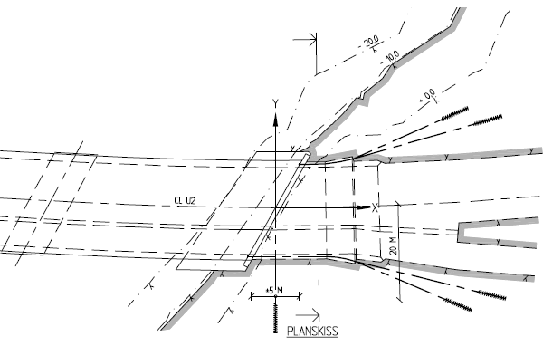
Plan of proposed Southern tunnel connection
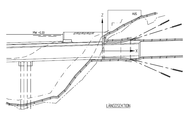
Elevation of proposed Southern tunnel connection.
CAD model geometry representing a 70m long x 80m wide x 50m high volume of rock and tunnel was imported directly into LUSAS prior to defining the material properties, supports and various loading conditions that needed to be assessed. To verify the model built, the coefficient of friction at the contact surfaces between the concrete tunnel and the rock was set to zero and a single load case with just the anchorage cable tensions was applied. From this, initial stresses in the rock around the anchorage points, and stress transfer and stress levels in the concrete and the rock heel could be evaluated. Because of the interfaces used in the model a nonlinear analysis had to be undertaken.
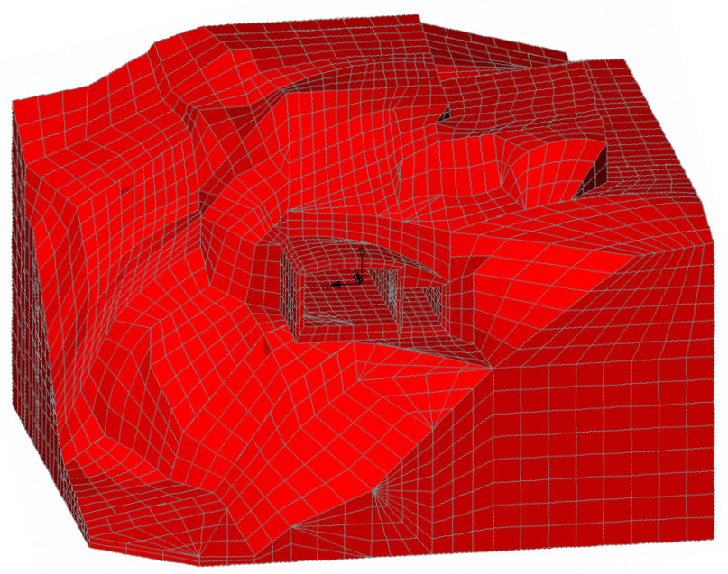
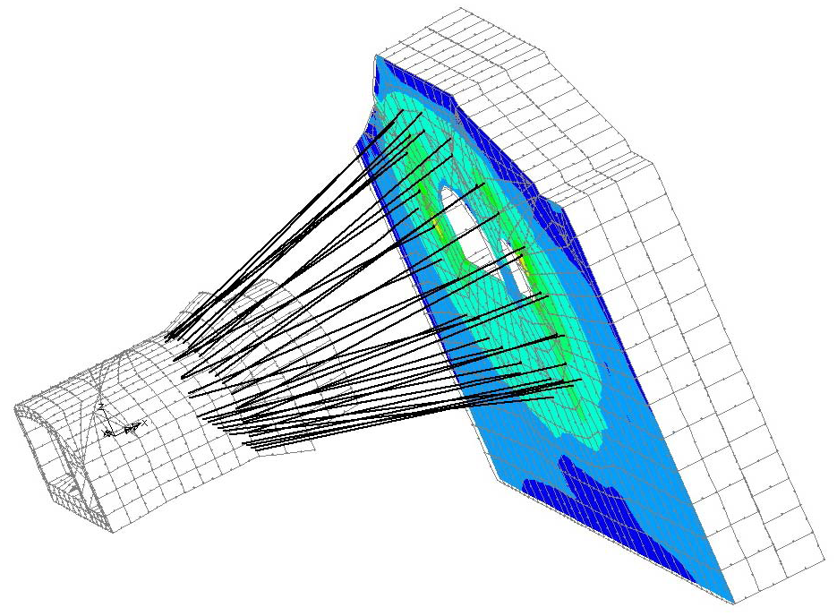
Solid modelling of rock and tunnel connector in LUSAS
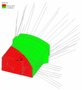
Tunnel connector model showing contact region (green) and location of longitudinal and transverse anchorages
For a number of the accidental loadcases considered, different coefficients of friction for the contacting concrete tunnel and rock surfaces were used to evaluate the effect on the results obtained. The effects of a horizontal or vertical displacement of the main tunnel, both of which apply a torque to the connector, and a longitudinal pulling force on the connector itself were examined in great detail, with stresses in the rock and anchorage cables, and stresses in contacting regions of the concrete and the rock being of particular interest.
Displacement and stress distributions calculated by LUSAS for these various loadcases and combinations were plotted on a number of slice sections through the model. In addition to slice sections at and in the vicinity of the cable anchorage points, horizontal sections were located at the mid-height of the tunnel, and at distances of 4.5m, 10m, and 15m below the tunnel base.
A longitudinal vertical section and a slice section inclined at 15 degrees towards Söderström (north) and 15 degrees to the east (to correspond with a fracture zone in the rock) enabled a detailed comparison to be made between the results from the LUSAS analysis and analytical results by others.
Stress distribution in the rock just behind the longitudinal cables
Stress in the rock at distances of 1m, 3m and 4.5m behind the transverse rock anchorages
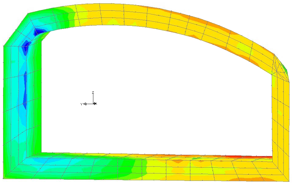
Stress distribution in the rock heel

LUSAS
Forge House
66 High Street
Kingston upon Thames
Surrey
KT1 1HN
United Kingdom
We only send occasional emails. Sign-up and stay up-to-date with the latest developments in the world of LUSAS..
LUSAS online sales Dismiss